Project DIY best series regulator/rectifier
for motorcycle
comparable to Shindengen SH775
From idea to realization
It's hard to find a serious regulator/rectifier manufacturer that will offer a quality DIY series motorcycle regulator project. We are seriously considering offering a do-it-yourself nonprofit project for everyone.
The reason is that there really are no such projects. There are some schemes that can be found on the Internet. Their main disadvantages are that they are poorly designed to withstand critical situations, poor voltage retention, use of electrolytic capacitors, difficult accurate voltage adjustment, high idle current consumption, etc. The goal is promotion, but also on cooperation, which is what our civilization is based on. In addition, in this way we fight against the flood of bad and fake regulators from China.
The project they would offer is a simplified version of the series regulator we produced 17 years ago. It would have the following characteristics:
- voltage from the stator: up to 110VAC
- consumption current: less than 160uA (1.3Ah/year)
- regulated voltage from 13.8 to 14.8V adjustable
- output current of the regulator up to 10 to 30A
- insensitivity to increased battery voltage up to 100V
- start operation if the battery voltage is higher than approx. 9V
- regulation to minimum or medium voltage (two connection versions)
- temperature stability: -5mV/°C or -0.7mV/°C depending on the connection version
- LED signaling: flashing or normal (not required for operation)
- LED signaling of stator breakdown on the housing when the regulator is connected
- LED signaling of the reached voltage
- resistance to the exchange of plus and minus polarity
- surge protection for input AC voltage 180Vp
- single-phase or three-phase version up to 8000rpm
- without electrolytic capacitors
- without protection from overheating
- the control electronics must not be heated above 85°C
- a rectifier typically consisting of three diodes for plus and three thyristors for minus
- thyristors are mounted without insulation, and diodes should have insulation
- in the event of a stator breakdown on the housing, the output voltage will not be controlled! The LED will then light up when the controller is energized and the motor is not running.
Extras:
- the possibility of using an additional wire for voltage measurements and switching on - ignition
- the possibility that the Kontakt+ additional wire controls the quiet consumption, regardless of which wire it measures the voltage on
- the possibility of easy connection of the output for an external LED diode (additional small circuit)
- the possibility of adding a circuit for an NPN or PNP output for a lamp with a current limit that turns on when the generator does not provide enough voltage or when it does not reach the voltage
- possibility of NPN or PNP tacho output for single-phase or three-phase version
- the possibility of an NPN output that is active when the stator provides voltage (Motor run out)
- possibility of external voltage adjustment (external resistor or trimmer connected to ground) or measuring wire for minus
- option for LED diode in series with contact wire that includes a standard/impulse regulator
- additional regulator assembly with grounded stator and protections
The difference in the sold product:
- consumption current: less than 68uA (0.6Ah/year)
- protection from overheating above 70°C
- high temperature stability
- LED standard
- regulated voltage fixed setting
- high quality polyurethane sealed in a robust heat sink
- start of operation if the battery voltage is higher than 6.2V
- stator voltage: 100 or 200VAC
- max engine speed: up to and over 8000rpm
It is prohibited and punishable by law without the author's permission to commercially reproduce, make available to others, use the project or modify it for commercial use. For commercial use or modification of our scheme, it is necessary to agree on the terms of cooperation.
The project we offer for do-it-yourself is our simplified earlier product that has already been practically tested 17 years ago and hundreds of regulators with an almost identical scheme have been sold. I believe that in many features it surpasses other professional replacement regulators. If you are really interested in a quality DIY series type regulator for charging a motorcycle, please contact me by e-mail with the subject "Best series DIY regulator/rectifier" and write what you think about the project? Would you be interested in the complete project (explanation of operation, schematic, control circuit board plan, possible modifications in application, assembly notes) remaining available for non-commercial use but for an affordable fee (20-30€). Additional circuit diagrams may also be available for an affordable fee. (e.g. typically €4 each or all together for €30). At the same time, we will not offer and provide an upgrade of the DIY project to the features of our commercial product. There is also the possibility of selling a kit that does not include a heat sink, potting compound, wires and power semiconductors that you optimally choose according to the application.
Of course, we are open to a one-time fee for non-exclusive use of our other projects for commercial purposes by agreement. For a slightly higher price, we could also offer DIY projects for other DIY regulators or even a collection of DIY projects. If there is a lot of interest via email, I will open a topic for discussion on our free forum.
DIY regulation electronics are usable for several types of stators: single-phase, three-phase and double single-phase (3 wires, one common) and stator voltages up to 110VAC.
DIY regulator, with a suitable heat sink and good moisture insulation, could be a good and safe replacement for the currently overpriced and hard-to-find Shindengen SH775. With the flood of fake Chinese copies, a DIY regulator of a good project seems like a winning combination. The quality and reliability of the regulator is literally in your hands. There are no unexpected surprises.
Used parts are easily found at electronic component suppliers. You can choose diodes and thyristors yourself (max 30mA gate trigger current). You only need to take care that the resistance of the thyristor to dU/dt should be 1000V/us.
Related articles
:
⦁ Advantages of the series regulator
⦁ Comparison of 3F HVSP regulator with Shindengen SH847
⦁ What to do when the voltage regulator on a motorcycle often burns out?
⦁ What to do when the stator on a motorcycle often burns out?
⦁ Control of the charging voltage of the 12V battery
⦁ Instructions for a quick solution to too low battery voltage

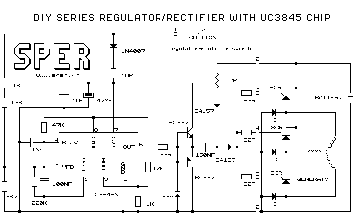
Example of free DIY simple series regulator/rectifier schematic:
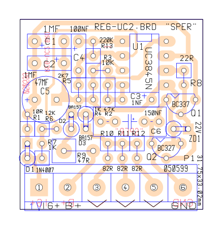
Control board layout
Warning: output voltage over 25V is dangerous for this simple regulator/rectifier above.
Motorcycle and outboard motor models for which you can make a DIY regulator/rectifier:
- AC Generator (regulator 14V-1F-15A-B), (regulator 14V-1F-10A-B), (regulator 14V-1F-20A-B-K-LO)
- Aprilia RS50 (regulator 14V-1F-10A-B) - installation needs to be changed due to switching the lights to DC voltage
- Aprilia RS128 red rose (regulator 14V-1F-20A-A)
- Aprilia 125 Pegaso 1993. (regulator 14V-1F-15A-A - maintains 14V on the battery, which even a correct original regulator cannot do)
- Aprilia 125 Tuareg (regulator 14V-1F-15A-A) - missing NPN lamp out!
- Aprilia 125 Tuareg (regulator 14V-1F-20A-A-LO) - NPN lamp out!
- Aprilia Pegaso 600 1990 (regulator 14V-3F-15A-B)
- Aprilia Pegaso 650 (regulator 14V-3F-15A-B); (regulator 14V-3F-15A-A), (regulator 14V-3F-15A-A-K)
- Aprilia Pegaso 650 IE (regulator 14V-3F-15A-A)
- Aprilia Pegaso 650 1997 (regulator 14V-3F-15A-A)
- Aprilia Pegaso 650 2001 (regulator 14V-3F-15A-B)
- Aprilia Pegaso 650 inj (regulator 14V-3F-15A-B)
- Aprilia Pegaso 650 2002. inj (regulator 14V-3F-15A-A)
- Aprilia Pegaso 650 cube 2000. (regulator 14V-3F-15A-B)
- Aprilia Pegaso 650 cube (regulator 14V-3F-15A-A)
- BMW ... (regulator 14V-3F-20A-A)
- BMW F650 (regulator 14V-3F-15A-A)
- BMW F650 1993. (regulator 14V-3F-15A-A)
- BMW F650 1996. (regulator 14V-3F-15A-A)
- BMW GS650F (regulator 14V-3F-15A-A)
- BMW Rotax (regulator 14V-3F-15A-A)
- Brix concrete screed (regulator 14V-3F-15A-B)
- Marine generator (regulator 14V-1F-15A-B), (regulator 14V-1F-20A-C-LD)
- Cagiva 350ccm / generator 160W/50VAC (regulator 14V-3F-15A-B) - installation needs to be changed if lights are on AC voltage
- Cagiva Mito 125 (regulator 14V-1F-15A-B) - need to change the wires connected to the starter box
- Chrysler 45 (regulator 13.7V-1F-10A-B outboard)
- Evinrude 35 3T 1990-2001 (regulator 14V-1F-30A-B outboard)
- Hatz diesel marine (regulator 14V-1+1FU-15A-B - designed for double half-wave or full-wave)
- Hatz (regulator 14V-1F-20A-A-K-LO+)
- Hatz vibrator (regulator 14V-1F-20A-A-K-LO)
- Hath 2G40H roller (regulator 14V-1F-30A-B)
- Hisun 350 (regulator 14V-3F-15A-B)
- Honda 125 (regulator 14V-3F-15A-B)
- Honda scooter ... (regulator 14V-3F-15A-A)
- Honda aggregate (regulator 14V-1F-10A-B)
- Honda CB250 (regulator 14V-3F-15A-A-KS - changes regulator, gretz and switch)?
- Honda CB500 (regulator 14V-3F-15A-B)?
- Honda CB500FT (regulator 14V-3F-15A-B)
- Honda CB500S (regulator 14V-3F-15A-B)
- Honda NSR 125R (regulator 14V-3F-15A-B)
- Honda NX400 (regulator 14V-3F-15A-B)
- Honda Shadow 750 (regulator 14V-3F-15A-B), (regulator 14V-3F-15A-A-KS)
- Honda Shadow 750 ACE (regulator 14V-3F-15A-B)
- Honda Shadow 750 2000 (regulator 14V-3F-15A-B)
- Honda Shadow VT750 C2 ACE (regulator 14V-3F-15A-B)
- Honda Shadow VT750 C (regulator 14V-3F-30A-B)
- Honda VT750 Black Widow (regulator 14V-3F-15A-A)
- Honda VT750 shadow 1997 (regulator 14V-3F-15A-A)
- Honda VT750 shadow (regulator 14V-3F-15A-A)
- Honda XL600 (regulator 14V-3F-15A-A)
- Honda XLR125 (regulator 14V-3F-15A-A)
- Honda XR125 (regulator 14V-3F-15A-A)
- Honda 6HP outboard (regulator 14V-1F-10A-B)
- Hyosung Comet 650 (regulator 14V-3F-15A-B)
- Hyosung Aquila 125 (regulator 14V-3F-15A-B)
- Hyosung Aquila 250 (regulator 14V-3F-15A-B)
- Hyosung GT250 (regulator 14V-3F-15A-B)! regulator is not for high revs!
- Hyosung GV250 (regulator 14V-3F-15A-B), (regulator 14V-3F-15A-A)
- Hyosung RX125 (regulator 14V-3F-15A-B)
- Hyosung Aquila GV250 (regulator 14V-3F-15A-B)
- John Deere tractor (regulator 14V-1F-20A-B-K-LO+)
- Johnson 25HP 2T outboard (regulator 14V-3F-15A-B)
- Kawasaki KLR250 (regulator 14V-1F-20A-A)
- Kawasaki VN750 (regulator 14V-3F-15A-A)
- Kawasaki VN900 (regulator 14V-3F-15A-A-K); (regulator 14V-3F-15A-A) - installation change required due to light relay
- Kymco Exciting 250 scooter (regulator 14V-3F-15A-A-KS)
- Kymco Zing 125 (regulator 14V-1F-15A-B), (regulator 14V-1F-15A-A), (regulator 14V-3F-15A-A-KS)
- Kymco 250 scooter (regulator 14V-3F-15A-B)
- Kymco MXU 250 quad (regulator 14V-3F-15A-B)
- Chinese motorcycle 150cc; 6000rpm (regulator 14V-1F-15A-A)
- Chinese quad (regulator 14V-3F-15A-B)
- Lawnmower (regulator 14V-1+1FGP-30A-B); (regulator 14V-1F-20A-B)
- KTM 450 (regulator 14V-3F-15A-B)
- KTM 640 LC4 enduro (regulator 14V-3F-15A-A-KS)
- Kubota 14D tractor (regulator 14V-1F-20A-A/3-T)
- Kubota working machine (regulator 14V-1F-20A-B-K-LO+)
- Linhai 520 twin (regulator 14V-3F-15A-B)
- Lombardini 6LD360 motor cultivator (regulator 14V-1F-10A-B)
- Lombardini 2Cyl working machine vibrator (regulator 14V-1F-15A-B)
- Mariner 25HP 1989 (regulator 14V-1F-10A-B outboard)
- Mercury outboard (regulator 14V-1F-10A-B)
- Mercury 4HP outboard (regulator 14V-1F-10A-B)
- Mercury 9.9HP 2T outboard (regulator 14V-1F-10A-B)
- Mercury 15HP outboard (regulator 14V-1F-10A-B)
- Mercury 20HP outboard (regulator 14V-1F-10A-B), (regulator 14V-1F-20A-A)
- Mercury 25HP outboard (regulator 14V-1F-10A-B)
- Mercury 30HP outboard (regulator 14V-1F-10A-B)
- Mercury 40HP outboard (regulator 14V-1F-10A-B)!, (regulator 14V-1F-20A-A)!
- Mercury 40HP 4T outboard (regulator 14V-1F-10A-B)!
- Motocultivator (regulator 14V-1+1F-15A-B); (regulator 14V-1+1F-30A-K-LO)
- Neuson 1402RD mini excavator (regulator 14V-1F-15A-B-LO with PNP output for lamp)
- Paraglider (regulator 14V-1F-10A-A-LDP+)
- Peugeot Jet Force 50ccm (regulator 14V-3F-15A-B)
- Piaggio X9 180 (scooter) 1991 (regulator 14V-3F-15A-B)
- Piaggio Liberty 200 (regulator 14V-3F-15A-B)
- Polaris 450 (regulator 14V-1F-15A-B)
- Polaris Phoenix 200 (regulator 14V-3F-15A-A-KS)
- Polaris outlaw 500 (regulator 14V-3F-15A-A)
- Working machine (regulator 14V-1F-20A-B-K-LO), (regulator 14V-1F-30A-B-K-LO)
- Working machine (regulator 14V-3F-30A-B-K-LO+)
- Shibaura P185F mini excavator (regulator 14V-1F-15A-B-K-LO+ on order = replacement for Denko RS5101)
- Suzuki DF6 6HP (regulator 14V-1F-10A-B outboard)
- Suzuki 9.9 (regulator 14V-1F-10A-B outboard)
- Suzuki 25hp (regulator 14V-1F-10A-B outboard
- Suzuki FOR 50HP (regulator 14V-1F-15A-A outboard)
- Suzuki Burgman 250 (regler 14V-3F-15A-A), (regler 14V-3F-15A-B)
- Suzuki DR250 1982 (regulator 14V-3F-15A-B)
- Suzuki DR600 (regulator 14V-3F-15A-B); (regulator 14V-3F-15A-A-KS)
- Suzuki DR600S 1985 (regulator 14V-3F-15A-B)
- Suzuki GSX250E 1983 (regulator 14V-3F-15A-B)
- Suzuki GSX750 EF 1985 (regulator 14V-3F-15A-A)
- Suzuki Intruder 1400 (regulator 14V-3F-15A-A
- Suzuki VN800 (regulator 14V-3F-15A-A)
- Suzuki XF650 (regulator 14V-3F-15A-A-KS)
- Sym HD200 scooter (regulator 14V-1F-15A-B; the choke that was connected to the generator was disconnected)
- Sym Husky 150ccm (regulator 14V-1F-15A-B)
- Takeuchi TB12 mini excavator (regulator 14V-1F-15A-B-LO with lamp output)
- Tasso mini car (regulator 14V-3F-30A-B-K-LO )
- TGB Access Apollo 300 (quad) (regulator 14V-3F-15A-B)
- Tohatsu M40c (regulator 13.7V-1F-10A-B outboard), (regulator 14V-1F-10A-B)
- Tohatsu 9.9HP two-stroke (regulator 14V-1F-10A-B outboard)
- Tohatsu 9.9D2 (regulator 14V-1F-10A-B outboard)
- Tohatsu 30hp 2 stroke (regulator 14V-1F-15A-A outboard)
- Tohatsu 30hp (regulator 14V-1F-10A-B outboard)
- Tohatsu 40hp (regulator 14V-1F-10A-A outboard)
- Tohatsu 45hp (regulator 14V-1F-10A-A 100°C outboard)
- Tohatsu 45hp (regulator 14V-1F-10A-B 100°C outboard)
- Tomo Vinković (regulator 14V-1+1F-15A-B) (without contact input and output for the lamp!)
- Tomo Vinković (regulator 14V-1+1F-30A-B-LO - output for lamp, no contact input!)
- Tomo Vinković (regulator 14V-1+1F-30A-B-LO-K - lamp output)
- Tomo Vinković (regulator 14V-1F-20A-B-LI), (regulator 14V-1F-20A-B-K-LO+)
- Tomo Vinković 420 (regulator 14V-1F-20A-B-LI)
- Tomo Vinković TV731 (regulator 14V-1+1F-30A-B-LO-K - lamp output)
- Tomos (regulator 14V-1F-10A-A 50W generator/50V at 5000 rpm outboard)
- Tomos 4.8 (regulator 14V-1F-10A-B outboard)
- Tomos 10 (regulator 14V-1F-10A-B 75W outboard)
- Tomos 18 (regulator 14V-1F-10A-A 50W outboard), (regulator 14V-1F-10A-B-T outboard)
- Trakor Ferrari (regulator 14V-1+1F-30A-B-LO-K)
- Tremix roller (regulator 14V-1F-10A-B)
- Roller (regulator 14V-1F-20A-B); (regulator 14V-1F-30A-B)
- Yamaha 125ccm (regulator 14V-3F-15A-A)
- Yamaha outboard (regulator 14V-1F-10A-B)
- Yamaha 5hp 2-stroke (regulator 14V-1F-10A-B outboard)
- Yamaha 6HP (regulator 14V-1F-10A-B outboard)
- Yamaha 8HP (regulator 14V-1F-10A-B outboard)
- Yamaha 8HP 4T (regulator 14V-1F-10A-B outboard)
- Yamaha 9.9HP (regulator 14V-1F-10A-B outboard)
- Yamaha 9.9HP 4T 1995 (regulator 14V-1F-10A-B outboard)
- Yamaha 15KS SEAL (regulator 14V-1F-10A-B outboard)
- Yamaha 15KS 4T (regulator 14V-1F-15A-A outboard)
- Yamaha 18HP (regulator 14V-1F-10A-B outboard)
- Yamaha 20KS (regulator 14V-1F-10A-B)
- Yamaha 25HP (regulator 14V-1F-10A-A 100°C outboard)
- Yamaha 25HP (regulator 14V-1F-10A-B outboard)
- Yamaha 25KS 4T 2006 (regulator 14V-1F-10A-B outboard)
- Yamaha 25KS 4T 2010 (regulator 14V-1F-10A-B outboard)
- Yamaha 30HP (regulator 14V-1F-10A-B outboard)
- Yamaha 40KS (regulator 14V-1F-10A-B outboard)
- Yamaha 40KS BED F40 (regulator 14V-1F-10A-B outboard)
- Yamaha 60HP (regulator 14V-1F-10A-B outboard)
- Yamaha 90KS (regulator 14V-1F-15A-B outboard)
- Yamaha F8CMHL (regulator 14V-1F-10A-B outboard)
- Yamaha HVR1100 (regulator 14V-3F-15A-B)
- Yamaha MT03 660ccm (regulator 14V-3F-15A-A)
- Yamaha RS250 (regulator 14V-1F-15A-A); (regulator 14V-1F-15A-B)
- Yamaha SR250 (regulator 14V-1F-10A-A 100°C)
- Yamaha Virago 125ccm (regulator 14V-3F-15A-A)
- Yamaha Virago 125ccm (regulator 14V-3F-15A-B)
- Yamaha Virago 250ccm (regulator 14V-3F-15A-B); (14V-3F-15A-A)
- Yamaha Virago XV250 (regulator 14V-3F-15A-A-K)
- Yamaha Virago XV535 (regulator 14V-3F-15A-A); (14V-3F-15A-B)
- Yamaha Virago XV535 1988 (regulator 14V-3F-15A-B), (regulator 14V-3F-15A-A)
- Yamaha Virago 750ccm (regulator 14V-3F-15A-B), (regulator 14V-3F-15A-A-K)
- Yamaha Virago 1000ccm 1985 (regulator 14V-3F-15A-A)
- Yamaha Virago 800/1000ccm 1995 (regulator 14V-3F-15A-B)
- Yamaha Virago 920ccm (regulator 14V-3F-15A-A)
- Yamaha Virago 1100ccm (regulator 14V-3F-15A-B); (regulator 14V-3F-15A-A-KS)
- Yamaha Virago 1100ccm (regulator 14V-3F-20A-A)
- Yamaha Super Tenere 750 (regulator 14V-3F-15A-B); (regulator 14V-3F-15A-A)
- Yamaha Tenere XTZ660 (regulator 14V-3F-15A-B)
- Yamaha Tenere XTZ660Z 1996 (regulator 14V-3F-15A-B)
- Yamaha TT600 (regulator 14V-3F-15A-A)
- Yamaha XT600E 1993 (regulator 14V-3F-15A-B), (regulator 14V-3F-15A-A)
- Yamaha XT660X (regulator 14V-3F-15A-B)
- Yamaha XVS125 dragstar (regulator 14V-3F-15A-A)
- Yamaha XVS125 dragstar (regulator 14V-3F-15A-B)
- Yamaha XVS250 dragstar (regulator 14V-3F-15A-B); (regulator 14V-3F-15A-A)
- Yamaha XVS250 dragstar 2001 (regulator 14V-3F-15A-B)
- Yamaha XVS250 dragstar 2003 (regulator 14V-3F-15A-B)
- Yamaha XVS650 dragstar (regulator 14V-3F-15A-B), (regulator 14V-3F-15A-A)
- Yamaguchi working machine (regulator 14V-1F-15A-A)
- Yanmar B17 mini excavator (regulator 14V-1F-15A-B-K-LO+)
- Yanmar B37 mini excavator (regulator 14V-1F-15A-B-K)
- Yanmar mini excavator (regulator 14V-1F-10A-B)
- Yanmar 1401 tractor (regler 14V-1F-20A-B-LO)
- Yanmar F14 tractor (regulator 14V-1F-20A-B)
- Yanmar F16 tractor (regulator 14V-1F-15A-B-K-LO+)
- Yanmar 3T72L-TBS (regulator 14V-1F-15A-B-LO+ with PNP output for lamp)
- Yanmar 3TNE68 (regulator 14V-1F-15A-B-LO+ with PNP output for lamp)
- Yanmar ... regulator RS1106 (regulator 14V-1F-15A-A)
- Yanmar ... regulator AM101406 (regler 14V-1F-20A-B-K-LO+)
- Yanmar (regulator 14V-1F-15A-B-K-LO+ with PNP output for lamp), (regulator 14V-1F-20A-B-K-LO+)
- Yanmar (regulator 14V-1F-15A-B)
- Yanmar (regulator 14V-1F-10A-B)
- Yanmar YM1802D (regulator 14V-1F-15A-B-LO+K with PNP output for lamp)
- Zohgyu Future 125 scooter (regulator 14V-1F-30A-B)
- Zongshen H2O 250 (regulator 14V-3F-15A-B)
- etc.
-
Home -
Regulators- All types of regulators
- 3FHVSP regulator/rectifier
- Quality
- List of replacement regulators
- Ordering
- Price list
- Aprilia Caponord ETV1000
- Aprilia Tuono 1000
- BMW F650
- Honda CBR 600 600F 900 1000 1100
- Hyosung GV250 GT250 GV650
- Kawasaki KLE500
- Piaggio Beverly 250 400 500
- Polaris Sportsman 570 850 1000
- Suzuki GSXR 600 750 1000
- Tomos 4.8 10 18
- Yamaha YZFR1 YZFR6
-
Publication-
Articles
- History of the 3FHVSP regulator/rectifier
- Replacement for Shindengen SH847
- Advantages of the series type regulator
- Project DIY best series regulator
- Battery voltage charging control
- What to do when the regulator/rectifier overcharges?
- What to do when the regulator often burns out?
- What to do when the stator often burns out?
-
Documentation
- List of regulators
- Price list of regulators
- Troubleshooting
- Guide for Quick Solution of Voltage Drop
- Comparison of SER/PAR Regulators
- Animation of SER/PAR Regulator
- 14V-3FHVSP-30A-AX/BX-KS-LI
- DP14V-3FHVSP-30A-AX/BX-KS-LI
- 14V-3FHVSP-30A-AX/BX-K2-LI
- 14V-3FHV-30A-A/B-LI
- 14V-3FHV-30A-A/B-LO
- 14V-3FHV-30A-A/B-T-LI
- 14V-3F-15A-A/B-LI
- 14V-1F-10A-A/B-LI
- DP14V-1F-10A-A/B-LI
- 14V-1F-15A-A/B-K-LI
- 14V-1F-20A-A/B-LI
- 14V-1F-20A-A/B-LO
- 14V-1F-20A-A/B-K-LI
- 14V-1F-20A-A/B-K-LO+
- 14V-1FHV-10A-A/B-LI
- 14V-1FHV-30A-A/B-LI
- DP14V-1FHV-30A-A/B-LI
- 14V-1FHV-30A-A/B-LO
- 14V-1FHV-30A-A/B-K-LO
- 14V-1FHV-30A-A/B-K-LO+
- 14V-1FHV-30A-A/B-T-LI
- 14V-1+1FHV-30A-A/B-LI
- 14V-1+1FHV-30A-A/B-LO
- HVSP flyer
- Prospekt reglera (croatian)
- Housing diagrams
- Education
- News
-
Articles
-
Troubleshooting -
Contact -
More -
Hrvatski